
CMMs: Making the Case for Higher Data Density

CMMs that have the ability to perform high-speed scanning offer a way to obtain higher data density — for more accurate measurements of production parts.
By Rich Knebel, Applications Engineer, Carl Zeiss IMT Corp.
Traditional CMMs are evaluated for their use in applications based on determining measurement uncertainty relative to the size of a workpiece and its required tolerances. Generally, the ratio is 10-to-1; in other words, the CMM should be 10 times more accurate than the tolerance it will verify. And CMM specs for measurement uncertainty are made relative to known or traceable artifacts such as gage blocks and ring gages. Because these artifacts are used to measure CMM performance, they must be more accurate than the CMM. Perhaps 10 times more accurate. As a result, they have near-perfect form, which is easily measured.
The accurate evaluation of imperfect form – the world of production parts – is much more demanding today, particularly with more complex parts and constantly rising accuracy demands. Because of that, there's a need for a better-equipped CMM – one that has scanning capabilities.
The science of metrology offers an answer, but it requires trading "good enough" practices for hardware and software solutions that are known to be better.
The existing metrology answer — and the future of measurement — is higher data density. The ability to acquire 800 sampling points instead of only eight. The tools that deliver this ability are high-speed scanning and superior, more robust mathematics.
Previously, scanning probes were available only on laboratory or premium-category CMMs. These systems required large capital investments, and the value-add was diluted by restrictive environmental parameters and slow cycle times.
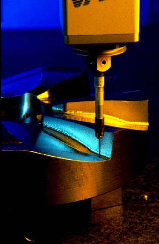
Today's scanning probes, by comparison, read hundreds of points in the time it takes touch trigger probe (TTP) CMMs to probe just four to eight points. When measuring the entire diameter of a 143.8 mm bore, for example, a high-speed scanning CMM can take 831 measuring points in 11 seconds. The 30-second scan of a 52.8 mm CNC-milled bore yields approximately 3,000 measuring points. And it can all be done on the shopfloor.
Function Follows Form
When measuring a near-perfect artifact, probe point quantities and locations are insignificant in calculating the result. In measuring production parts, however, CMMs inspect imperfectly formed features and then mathematically relate sampled points to geometric elements like circles, planes, and cylinders. The result can vary according to where the CMM samples each feature. This means the quality of size, location, and form information is directly related to the number of samples and the location of each point.
Most people understand the need for high data density when evaluating form. It is not as well known that form must also be understood in order to provide truly accurate location and size evaluation. If you don't know true form, you can't know the functional size and location.
Form deviation is present in all features. It's the magnitude of the deviation that varies. An example using a two-lobed diameter shows that functional size can be affected by as much as one-half the form deviation when using only four sample points (See diagram.). Measuring a common three-lobed diameter with only four points shows an error in size that is approximately 70% of the form deviation. The error in location is approximately 60% of the form deviation.

These errors are significant when compared to the 10–to–1 rule for desired gage accuracy. Even in these simple, common applications, the error directly attributable to low data density can be as great, or greater than, any error inherent in the CMM. That's why it requires a minimum of 300 points to evaluate a form like the circularity of a diameter in the 25–70 mm (1–3 in.) range. This level of data density is the minimum necessary to determine 90% or more of the correct form value.
The Power is in the Math
A Zeiss study compared results from an existing TTP program to results using a scanning probe. Zeiss scanning methods also employ alternate algorithms, not the commonly used Least Squares (Gauss) mathematics. The TTP and scanning methods were both applied to a cast iron pump housing. Both methods were executed using the same CMM.
For 18 of the 45 characteristics included in the study, results from the two methods differed by more than 10% of the tolerance range. In eight of those instances, scanning-enabled high data density inspection identified out-of-tolerance characteristics which "passed" under the TTP method. The potential error from low data density is even larger given that most measurements are not simple, 2D entities. Three-dimensional form variations of workpieces must also be considered.
The limitations of low data density and Least Squares mathematics came to light a decade ago, when a GIDEP Alert addressed potential problems in inspection methods that stray from the functional intent of an engineering drawing. The Alert confirmed that Least Squares math is not the most correct way to evaluate flatness, straightness, parallelism, and perpendicularity.
The problem, however, extends beyond those four characteristics. Least Squares does not provide a functional size or location. And it does not evaluate form properly. The ultimate requirement — the contemporary solution — is better mathematics.
If CMM manufacturers know that Least Squares are not the optimum mathematical algorithms, why are they used? The answer is that the algorithms that are "more correct" require very high data density to produce stable and reliable results. Other methods — Maximum Inscribed elements, Minimum Circumscribed elements, and Minimum Zone elements — each have a specific purpose. And given enough data, they produce considerably improved functional results. Least Squares is simply the best available solution for producing repeatable results when dealing with low data density.
High Density and Improved Process Control
In their role as process control gages, CMMs are evaluated with Gage Repeatability and Reproducibility (GR&R) tests. A GR&R can be a more difficult test of accuracy than identifying measurement uncertainty. This is because GR&R tests are conducted on production parts instead of traceable artifacts. The parts have form errors, which affect the ability of a sampling device to generate the same answer when multiple parts are measured multiple times by several operators.
Once again, high data density is the solution. Sampling several hundred points significantly improves GR&R results by eliminating dependency on where the data is taken from one trial to the next.
In a GR&R test that compared a high data density scanning CMM to a low density TTP CMM, Zeiss measured an aluminum electric motor housing. The test checked 29 characteristics in a two-operator, three-trial study. The high data density solution repeated approximately twice as well as the low data density method. Reproducibility was approximately 10 times better. The highest improvement in a measured characteristic was 75% for a projected true position. High data density improved the results for five other characteristics by 20% or more. Overall, the improvement averaged 11%.
Conclusion
Eventually, every manufacturing organization that wants to improve products and processes will migrate to high data density systems. Using high data density to generate better functional evaluations of size and location enhances outcomes from identifying assembly problems, to reducing warranty cost exposure. The key is understanding that the influence of form on size and location can be greater than any error inherent in a CMM.
Adding this consideration to the 10–to–1 gage tolerance rule improves the ability to select an inspection engine (high data density) and a methodology (high-speed scanning) that provide the best chance to stay within the tolerance range — repeatedly — on imperfectly formed production parts.
About the Author
A 20-year veteran of Carl Zeiss IMT Corp., Rich Knebel currently serves as manager of strategic development. He's held various positions at Zeiss, including technical sales manager, software development manager, and applications manager. Previously, Knebel worked as a quality engineer at Pratt & Whitney.